Where Does the Load Live and Traveller Wire Go on a Switch
Dear Mr. Electrician: I need to see some three-way switch wiring diagrams. I have two switches that control one light in my kitchen. I am not sure if they are 3-way switches or 2-way light switches. I find that one switch has to stay in the up position at all times just so the other switch will turn on the light. How do I diagnose and fix this?
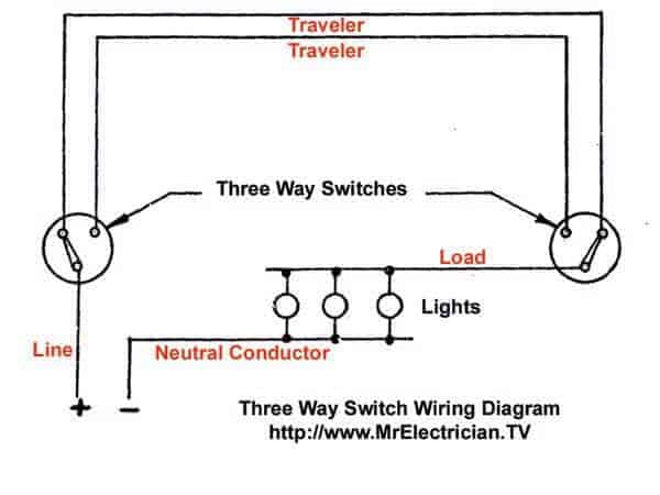
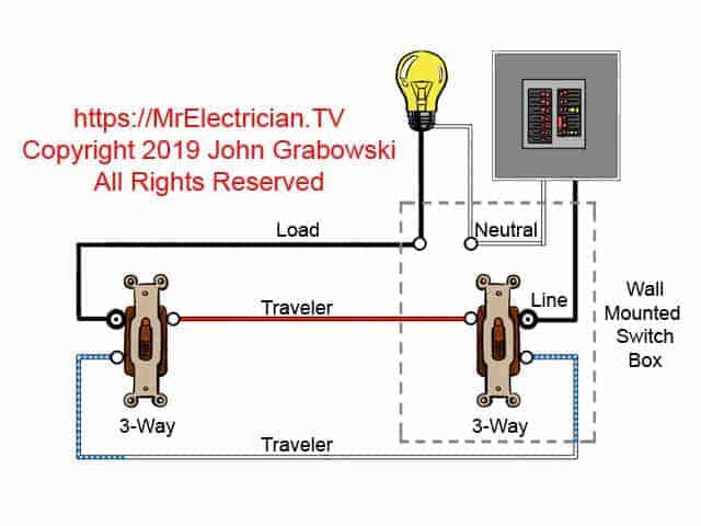
Answer: This blog post has a few three-way switch wiring diagrams along with some good advice. One diagram is above, the rest are below. NOTE: Some text links below go to applicable products on Amazon. As an Amazon Associate I earn from qualifying purchases.
Two-way electrical light switches and 3-way light switches are the same thing, they just have different names according to country. I am guessing that one of your three-way switches broke down.
Shut off the electrical power for the circuit at the circuit breaker box. Due to multiple wires being hot in this particular type of switch wiring it can be a little tricky for an amateur to diagnose which 3-way switch failed.
Assuming that the 3-way switches were wired correctly, I suggest that you change one switch. If that doesn't fix it, then change the other one.
I usually take one wire off the old switch at a time and put it on the new switch then repeat with the other wires. Please note the different color screw terminals. It's a good idea to replace both switches at the same time as the other one could fail soon after.
If the 3-way switches were not correctly wired, then you must be very careful to identify the LINE and LOAD wires BEFORE you disconnect the switches. LINE is the power and LOAD goes to the light or other things controlled by the 3-ways.
The LINE wire will be hot or live with electricity at all times regardless of the 3-way switch positions which makes it the easiest to identify. Use a voltage tester with two leads or a pigtail light socket with an incandescent or halogen light bulb.
Non-contact voltage testers may give you false readings due to the close proximity of the wires on the switch. It is best to remove the suspected hot wire from the screw terminal to test it with a non-contact voltage detector.
Wear insulated electrical gloves when working with live electrical circuits.
Click here for my blog post about working around your home safely.
Do not remove all of the wires from the one three-way switch at once and then try and figure what each wire is. First thing is to take notice of the color of the screw terminals on the old switch.
One screw terminal will have a different color and will be labeled "Common". That screw should have either a LINE or a LOAD wire connected to it.
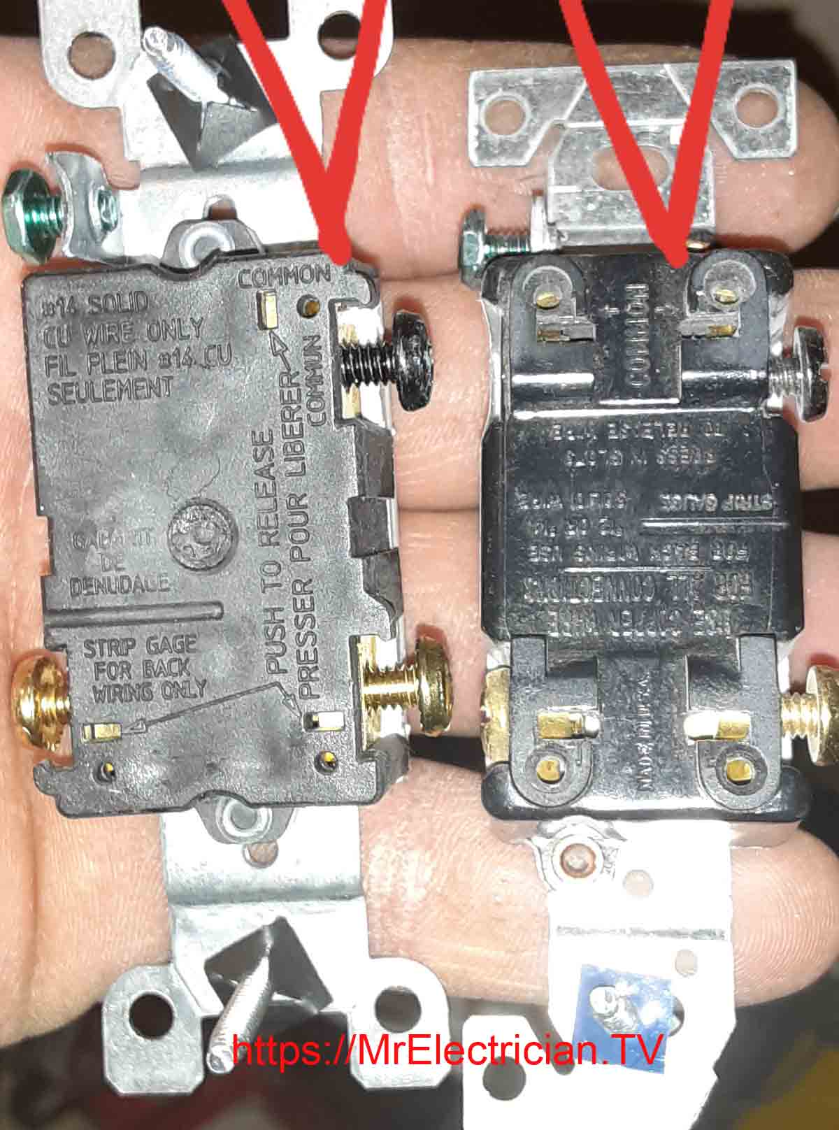
Thank you to John S. for the above photo depicting the common terminals on three-way switches. The common terminals are the ones with the different color used for LINE and LOAD. The unlabeled brass terminal screws are for the traveler wires to get connected to.
You cannot rely entirely on the color coding on three-way switch wiring diagrams to figure out what each wire's function is in an existing 3-way switch installation. The original installers used whatever materials and wiring methods were acceptable at the time of installation.
There are old existing 3-way electrical switch installations that do not follow acceptable industry practice or electrical code requirements. That is why it is important to identify the function of the wires for 3-way electrical light switches.
Changing a 3-way switch to a WiFi smart switch can be tricky. You will need a white neutral conductor to power the smart switch. You cannot use the bare or green grounding conductor instead of a neutral. In addition some changes may need to be made at the other 3-way switch in the circuit.
Most likely the LOAD and one traveler will need to be connected together while the other traveler is capped with a wire connector. Every smart switch will be different and you must follow the manufacturer's installation instructions.
Before buying a smart switch I suggest that you check the manufacturers website for the installation instructions. Read the instructions before purchasing the smart switch.
COMPONENTS OF THREE-WAY SWITCH WIRING
All three-way switch and 2-way switch wiring diagrams have the same basic components: Wires consisting of a LINE, a LOAD, a neutral, a pair of travelers, and two 3-way switches. If you are trying to troubleshoot a 3-way switch operation, you will need to identify the function of each wire. Do this before you disconnect any wires from the switches.
The LINE wire is usually the easiest to identify because it is hot at all times. It should be terminated on a common copper or black screw on one of the 3-way switches. The other three-way switch will have the LOAD wire connected to the common copper or black screw. A voltage tester is good for testing the live wires with neutral and/or earth ground.
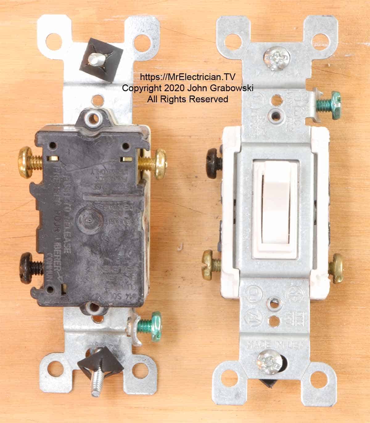
Note the one black screw on each of the above three-way switches. Only the LOAD wire or the LINE wire gets terminated on the common black screw. The green screw is only for grounding purposes and must have only one ground wire connected to it.
Click Here to see all of the Three-Way Switches Available on Amazon
It is possible to simply replace the switches without having to identify the function of each conductor. In this case you would just remove one wire at a time and put it on the same terminal on the new switch. Take note of the color of the screw terminals on the old and the new switches. Check the rear of the old switch for the "Common" terminal.
With older wires where the color is not very distinguishable, I use colored electrical tape to identify the conductors. It is very helpful and makes replacement much easier the next time the switches need to be changed. I always have black, white, red, green, and blue electrical tape on my truck.
Between each three-way switch is a pair of "Travelers" that are connected to the unlabeled brass terminals. The traveler wires are interchangeable between the two brass colored terminal screws.
On one of the 3-way switches a LINE or hot wire gets connected to the common copper or black screw terminal. On the other three-way switch the LOAD wire (The LOAD is the wire that feeds power to the light fixture) gets connected to the common copper or black screw terminal.
Below is a simple three-way schematic that can be applied to all three-way electrical light switch connections. This is only a wiring schematic and not the actual wiring method used for 3-way switch installations.
More three-way switch wiring diagrams depicting actual wiring methods are further down.
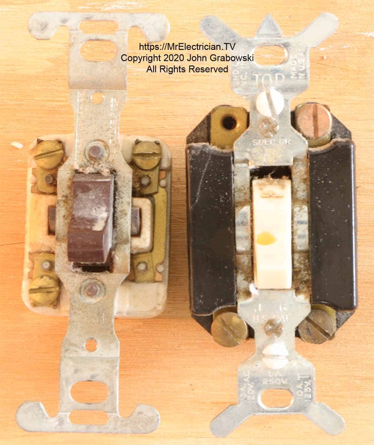
Two very old three-way switches are depicted in the photo above. The screw terminals were on the front of switches many, many years ago. This was unsafe having live electrical terminals so close to a metal wall plate. I have personally seen a few instances where the metal wall plate was coming in contact with the live terminals and creating a short circuit resulting in a tripped circuit breaker.
MORE THREE-WAY SWITCH WIRING DIAGRAMS
There are several three-way switch wiring methods that can be used and it is usually the installer that determines what is the best way for his or her purposes. In some countries the three-way switch is called a two-way switch. The National Electrical Coderequires that a neutral conductor (White wire) be installed at most new light switch locations however article 404-2(C) only requires the neutral at one 3-way switch location.
The three way switch wiring diagram depicted at the top of this post is probably the most common method for wiring three-way switches. The two-wire LINE cable goes into one switch box and the two-wire LOAD cable goes into the other switch box. A three conductor cable with a groundis then installed between the two 3-way switch boxes.
This method is also code compliant with regard to box fill and the number of wires that each electrical box is limited to having inside.
At the LINE switch box, the black wire of the two wire LINE cable gets connected to the common copper or black screw terminal on the three-way switch. The red and black wires (Travelers) of the 3-wire cable get connected to the brass terminals on the three-way switch. It doesn't matter which traveler goes on which brass terminal.
The white LINE neutral wire gets connected to the white wire of the 14/3 cable. At the other end the white LOAD neutral is connected to the white wire of the 14/3 cable. At the LOAD switch box, the black wire of the two-wire LOAD cable gets connected to the common copper or black terminal on the three-way switch. The white LOAD wire gets connected to the white wire of the three-wire cable. The red and black travelers in the 3-wire cable get connected to the brass terminals on the three-way switch.
The above method is good because it ensures that the white LINE neutral conductor is available at each switch box. In addition this method requires only a 3 conductor cable (With ground) between the switches.
Not every existing 3-way switch installation has the same wire colors. It is important to identify the LINE and LOAD wires before replacing 3-way and two-way light switches. Take notice which wires are connected to the common copper or black screw terminals.
A variation of the above three-way and 2-Way switch wiring is to bring all of the cables into one wall switch box as depicted in the diagram below, and branch off from there to each switch and light fixture.
The LINE and LOAD are brought into one 3-way switch electrical box. From there a 3-wire cable (2 travelers, a ground, and the re-identified white wire) or a conduit would need to be installed over to the second 3-way switch.
Whenever the white wire is being used as something other than the neutral conductor it must be changed to a different color. At the second 3-way switch, the black wire would be connected on the common copper or black screw terminal on the switch.
The bare or green wire is connected to the metal switch box with a 10/32 machine screw, and onto the green screw on the 3-way switch. The bare or green grounding conductor is not shown in these wiring diagrams in order to keep them simple.
Click here to see my blog post about outlet and switch grounding.
The electrical box must be big enough to accommodate the number of wires. See Article 314 in the National Electrical Code (NFPA 70) for space requirements.
In the above diagram the white wire must be re-identified as a hot wire at each switch location. The white wire between switches is not being used as a neutral. Use a colored electrical tape or a permanent ink maker to change the wire color.
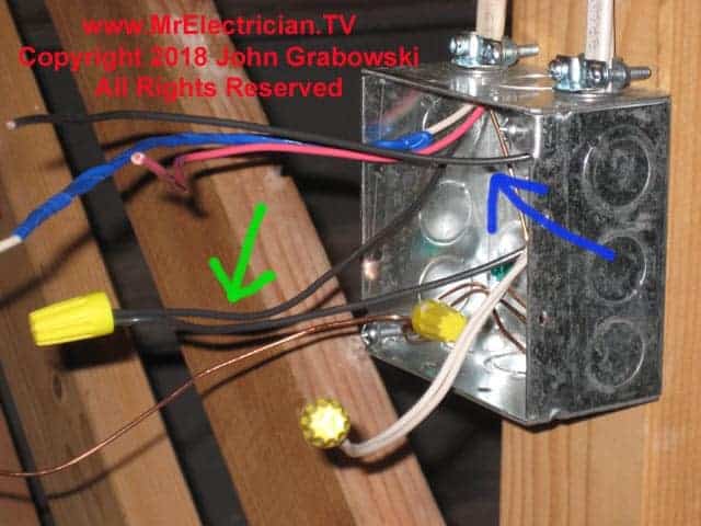
In the photo above the green arrow points to the LINE hot wire connected to the black wire of the 14/3 cable that is going to the other 3-way switch. The blue arrow points to the LOAD wire which will be connected onto the common black or red colored terminal on the 3-way light switch to be installed in this box.
The red and blue wires in this installation are the travelers. This was added to an existing installation that only had one single pole wall switch at the top of the basement stairs for the basement lights. The homeowner wanted an additional switch in the basement.
The photo below shows the wiring at the other 3-Way location which was a single pole switch originally.
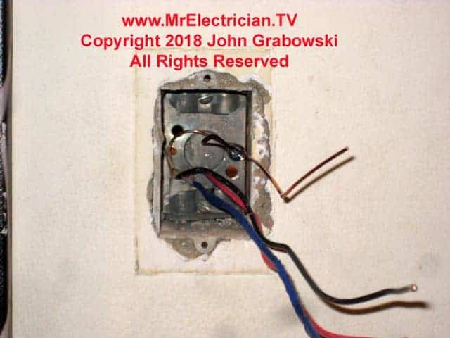
The black hot wire in the electrical box above is connected at the other end to the black LINE wire and gets connected to the common black or red screw on the 3-way switch. The white wire has been taped with blue electrical tape to show that it is not a neutral conductor, but a traveler. The red wire is the other traveler. The travelers get connected to the two brass screw terminals on the 3-way switch.
When a white wire is being used as a traveler, it needs to have its color changed according to Article 310.110(C). Any color but white, gray, or green can be used. The extra clamp at the top of this switch box needs to be removed as it counts as one additional wire (Article 314.16(B)(2).
At the first switch box, the black wire that was run to the second 3-way switch can be connected to either the black LOAD wire or the black LINE wire. The black LINE wire or LOAD wire that is not connected to the second 3-way switch, gets connected onto the common copper or black terminal of the first 3-way switch.
The LINE and LOAD white neutral wires should be spliced together. The traveler wires from the second switch get connected to the same two brass terminals on the first switch.
The ground wires should all be joined together and one or two pigtails connected from that bunch should be connected to the metal box with a 10/32 machine screw and to the green screw terminal on the 3-way switch.
Another example of an alternative 3-way wiring method is to bring all of the cables into the ceiling light fixture electrical box. From there a three conductor cable or a conduit would need to be installed to one of the 3-way switch locations. A four conductor cable with ground or a conduit would need to be installed to the other 3-way switch location as required by code to have a white neutral conductor in one of the switch boxes.
A larger ceiling electrical box would be needed to accommodate all of the wires in this particular 3-way switch installation. A minimum of 24 cubic inches is required if #14 wire is used. See Tables 314.16(A) & (B). Two cubic inches are required for each #14 wire.
An update in the 2020 National Electrical Code requires that all ceiling light electrical boxes where a ceiling fan could possibly be installed must be rated forceiling fan support. See article 314.27(C).
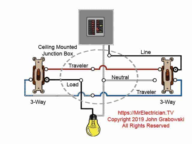
At each switch in the above 3-way switch wiring diagram the black wire gets connected to the common copper or black screw. In the ceiling light fixture electrical box, one black wire from a 3-way switch gets connected to the black LOAD wire on the light fixture. The black wire from the other 3-way gets connected to the LINE black wire. The LINE white neutral wire gets connected to the light fixture.
The travelers in the ceiling light junction box get spliced through color to color. The grounds are connected together, to the metal box, and also to the light fixture. The ceiling electrical junction box needs to be extra large to fit all of the wires. Take note of the white neutral wire that is required to be in one of the switch boxes.
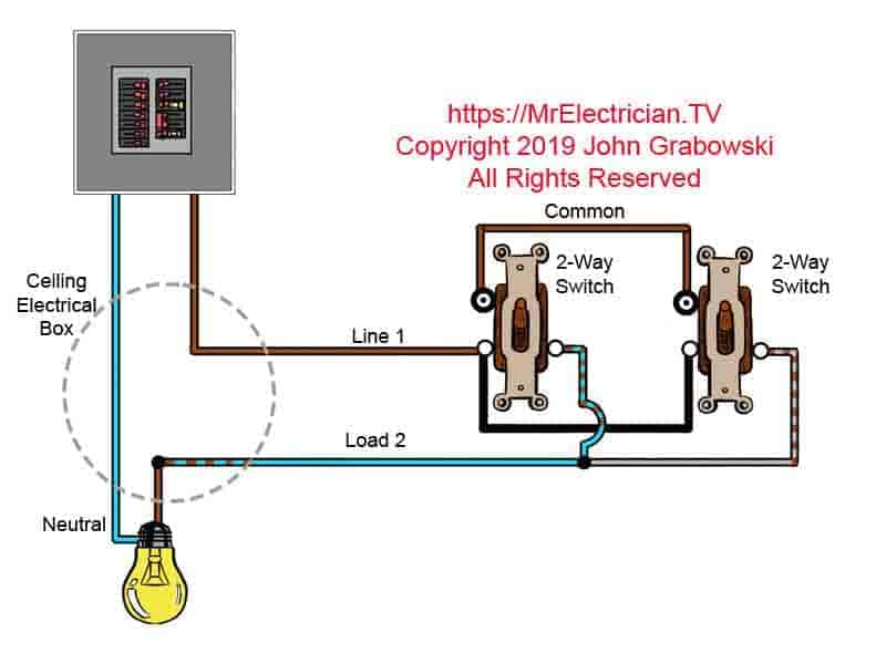
In the United Kingdom some electricians use an alternative method for wiring two-way switches as depicted in the above wiring diagram. Two-way switches and three-way switches operate the same way and have the same connection points, they just have different names in the UK which are Common, L1, and L2.
The above switch wiring diagram shows a different wire color coding than what is used in the USA. In this wiring configuration the Common terminals on each 2-way switch are connected together with one wire. The LINE wire is connected to the L1 terminal and the LOAD wire is connected to the L2 terminal.
If you wanted to add more switches you would install four-way switches, or as they are called in Europe, intermediate switches which get wired to the L1 and L2 wires. The intermediate switches are wired in between the two-ways. Using a three core cable, the Common wire going to the 2-way switches just passes through each intermediate switch electrical box. Colored electrical tape is used to re-identify the wires.
The ground wires are not shown on these diagrams to save space and make for easy viewing. However during the installation, all ground wires would be joined together and a pigtail for each switch would be added. All metal electrical boxes need grounding with its own grounding pigtail using a 10/32 machine screw in the back of the box.
You might find my post depicting 4-Way switch wiring diagrams useful.
If you are planning to install a ceiling fan, visit my blog post depicting ceiling fan wiring diagrams for additional guidance.
For single pole light switch wiring diagrams see my post here.
To wire wall switches to control electrical outlets, see my post here.
Where Does the Load Live and Traveller Wire Go on a Switch
Source: https://mrelectrician.tv/three-way-switch-wiring-diagrams/